The Ultimate Guide to Transferring the Model from CAD to CAM
August 2023
7 min
Product Development
Engineering
Uncover the key principles for shifting your model from CAD to CAM in new product development. Expert tips for mastering design engineering.
In today's fast-paced world, creating a 3D model in CAD programs is only half the job when developing a new product. While providing services for startups, outsourcing companies must ensure tangible hardware prototypes, not just aesthetically pleasing virtual models. This is where CAM software, a powerful tool for automated manufacturing, comes into play by facilitating the conversion of computer models into physical prototypes. With the help of CAM software, the CNC machine receives precise instructions on the tool's trajectory during the workpiece processing, ultimately yielding the desired part.
Before initiating the transfer of a model from CAD to CAM, it is imperative to adequately prepare the model using various CAD programs. By preparing the model effectively, future errors are avoided, streamlining the CNC programming phase. This part of the new product development process will be explained further in greater detail.
Consider Manufacturing Capabilities First
During the design engineering process, it is essential to determine the manufacturer of the part and learn about the limitations imposed by their equipment. Whether you have a restricted choice of technologies or employ proprietary equipment, the following aspects must be taken into account while tuning the model in CAD programs:
Material. The equipment employed must be suitable for processing the chosen material while possessing the necessary properties required for the final application.
Tolerances. Designing a part for specific machines necessitates considering the tolerances of both the part and the equipment itself. These limitations should be factored in during the development of a product.
Part's shape. Dimensional considerations and machine capabilities must be taken into account when designing the part. A 5-axis CNC machine provides greater freedom in part shape compared to a conventional 3-axis CNC machine. If the part exceeds the working field dimensions of the machine, it is advisable to plan it as a prefabricated one.
Check CAD Models for Integrity
Before transferring a 3D model to a CAM software, it is vital to verify its structural integrity and eliminate any errors. We have extensively covered this topic in our article on 10 things we usually redo in startups’ CAD models before manufacturing. When checking the models, the following aspects should be examined using the built-in utilities of the CAD software:
coaxial alignment of holes
absence of faces or edges
auxiliary geometry
An example of an error is depicted in the following figure.
Deviation of the coaxial alignment of holes
Check the Models for Discontinuities and Open Curves
It is vital to inspect 2D models for discontinuities and open curves as they can lead to processing errors. You can check the models using the built-in CAD software utilities. If the errors are not eliminated, they will affect the finished part and the workpiece will be damaged.
Example of discontinuities
Remove the Unnecessary after Designing
Before sending the model to CAM, open and save the part to a separate file. In doing so, all extraneous components can be efficiently removed from the model. This practice expedites the processing of the CAM model by the software, mitigates the occurrence of future errors, and safeguards the workpiece. Examples of unnecessary elements are demonstrated below:
Unused Elements
Rough sketches, study elements, selected components and other elements of the model that remained after the design activity should be removed from the final geometry. It is also recommended to remove geometry that may be far outside the main part of the drawing. Otherwise, if you don't notice it in the process of pre-modeling the milling cutter's trajectory, you can start cutting the model in the wrong places. This is a common problem for novice technologists and operators when an imprecise model comes from the designer.
Unused element in the part model
Remove Invisible Elements
Invisible elements, such as dots, empty components, invisible/overlapping lines, hidden model attributes, increase the file size and require additional time for their processing by the software. All invisible elements can be removed through the construction tree. When you select a part from the main assembly into a separate component, review the construction tree and remove all unnecessary things from there. Ideally, only one relevant element of the part to be processed should remain.
Invisible elements
When uploading a 2D file with overlapping/invisible lines to the CAM software, it will process them and hold the processing tool in this place several times, which will increase the processing time of the part.
The green line is superimposed on a solid blue line
With all superfluous elements removed, it is now safe to name the file "For production" and transmit the model to the technologist.
Configure the CAM Model as a Technologist
If you are not going to give the model you have developed to an outsourcing company, you will have to configure the model in CAM yourself. Each model is unique and needs to be considered separately, but the principle of operation in CAM is the same.
Tool Setup
Should you decide against outsourcing services, remember the crucial step of tuning the tool for optimal results. The processing of the part is accomplished by employing multi-blade tools, specifically milling cutters. After you have loaded the model into the CAM and finished preparing the control software, check the tools you have selected. It is important to take into account the tolerances and quality of surface treatment that are necessary for the final product, as well as restrictions on material and cutting speed. In the documentation for the equipment, the manufacturer usually prescribes processing speeds for various materials and tools, so you can see them there.
Process Modeling
Before commencing workpiece processing, it is vital to simulate tool trajectories within the CAM software. This simulation aids in identifying potential problems and errors, including tool collisions with the workpiece or incompatibilities with the model's geometry. Process modeling can help avoid costly errors and minimize the risk of equipment or workpiece damage. At the initial stages, we advise you to view the entire process of processing the material at a low playback speed to make sure that the selected trajectories are correct.
Simulation of workpiece processing
In closing
At first glance, the process of transferring a model from CAD to CAM is simple, but without a thorough understanding of the intricacies involved, can at best impede the processing workflow and at worst damage the workpiece or equipment. It is necessary to think about the production method of a part even before the start of its development in order to take into account all the limitations associated with the equipment. After development, the part must be checked for integrity and cleaned of unnecessary elements. After CAD modeling and transferring the file to the CAM software, the processing tools should be reviewed, and a thorough simulation of the workpiece processing should be conducted to ensure error-free production.
Fresh, cool, new insights from EnCata in engineering every month
Thank you! Your submission has been received!
Oops! Something went wrong while submitting the form.
Learn more from our insigths
Engineering
Product Development
Startup
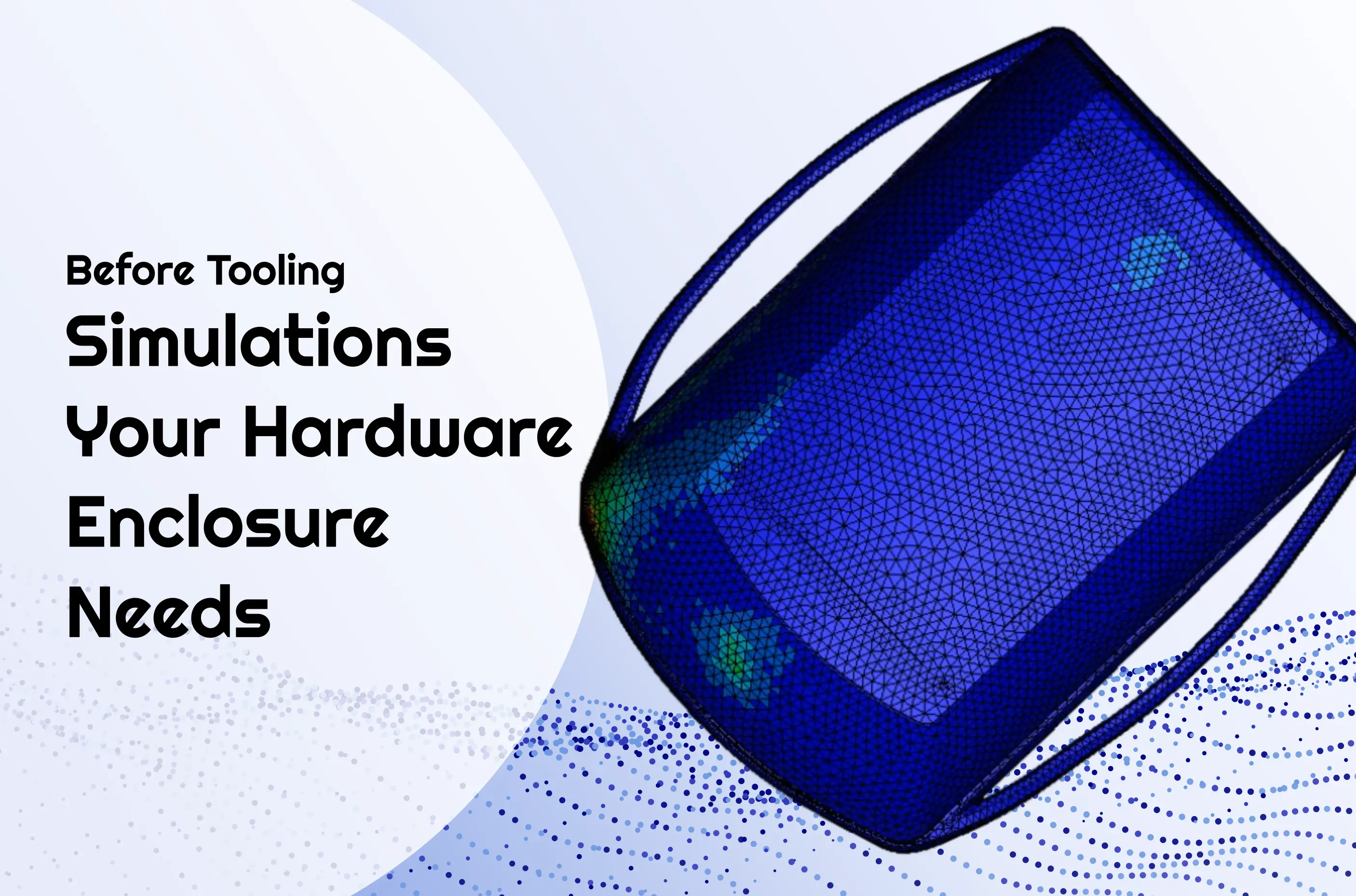
Essential Simulations Your Hardware Enclosure Needs Before Tooling
Essential simulations for first-time hardware product founders: thermal analysis, drop testing, vibration analysis, and CFD. Reduce risk, cut iteration costs, and ship reliable products from day one.
Product Development
Engineering
10 things we usually redo in startups’ CAD models before manufacturing
Learn the 10 most common product design mistakes that threaten manufacturability. This article is brought to you by EnCata’s Business Development specialist Pavel Avramenko.
Product Development
Hardware
Fixed Price vs. Time and Materials: Finding Your Project's Best Fit
No matter how many products you’ve built, you may wonder: How do I collaborate effectively with contractors? Click to explore Fixed Price and Time & Materials!
Have a project to do?
Fill out the form and a member from our sales team will get back to you
Thank you! Your request has been submitted! We shall contact you shortly
Oops! Something went wrong... Try to reload this page and resubmit
FAQ
At EnCata, what kinds of contracts do you use? Is it a fixed-term or an agile contract?
Can you provide me with a certification of competence?
What level of training do your specialists have?
Is it possible for us to cooperate with EnCata’s team?
Is it possible to discuss the project with your technical team?
Can EnCata facilitate mass production?
Do you sign NDAs?
Patent or Develop first?
Does EnCata outsource electronics services?
Do you write program code, either software or firmware?
Are there hardware engineers in your team?
What should I do now that I've approached you with my project idea?


%201%20(1).jpg)
.jpg)


